HCCM-2100 - Heater Cable Control and Monitoring System
Installation Manual - HCCM-2100 Addressing Procedure
Previous Section | Table Of Contents | Next Section
General
The Local Control Panel is supplied with Network Controller(s) and Input/Output Module(s) already addressed. The identification on the panel indicates the Network Controller (NC) ID. Remote Terminals are addressed after the installation.-
Install all the Remote Terminals as described earlier in this
manual.
-
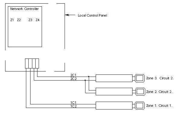
Mark the ends of the heat tracing cable circuits as they
are connected to the Local Control Panel. For example, heat tracing cable circuit
connected to 1C1 and 1C2 is marked "Circuit 1", heat tracing cable circuit
connected to 2C1 and 2C2 is marked "Circuit 2", and so on.
- In the event of branched heat tracing cable circuits,
identify all Remote Terminals connected to the same circuit with the same
circuit number.
- Identify Remote Terminals by Zone numbers, corresponding to the zone numbers in the Local Control Panel, whether they are installed on branched or individual heat tracing cable circuits.
Addressing Procedure
-
Disconnect and lock out all power circuits before working on the Remote
Terminals.
- Note the Network Controller (NC) ID
identified on the Local Control Panel.
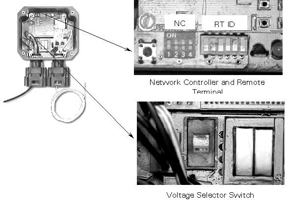
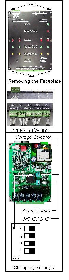
- Remove the Remote
Terminal cover to expose the printed circuit board and the addressing dip
switches.
- Set the
NC ID dip switch as indicated noted from the Local Control
Panel.
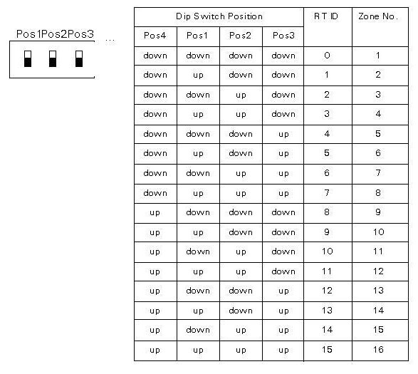
- Set the
Remote Terminal dip switch as per Zone markings made earlier (see Table
2).
- Set
the Voltage Selector Switch to proper voltage (115V or 230V).For 208, 230 and
277V systems use 230V setting.
- Close
the cover and tighten the screws on the Remote Terminal.
- Mark the weatherproof label (provided on the Remote Terminal cover) as per settings made with permanent marker.
Dip Switch Addressing
Table 1. Network Controller (NC) ID.
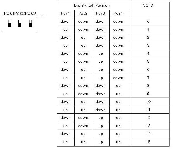
Table 2. Remote Terminal (RT) ID.
 |
Adding Zones
|